Section 6 of 15
Section 5: Air Brakes
This section tells you about air brakes. If you want to drive a truck, bus, or pull a trailer with air brakes, you need to read this section. If you want to pull a trailer with air brakes, you also need to read Section 6: Combination Vehicles in this handbook.
Air brakes use compressed air to make the brakes work. Air brakes are a good and safe way of stopping large and heavy vehicles, but the brakes must be well maintained and used properly.
Air brakes are really 3 different braking systems: service brake, parking brake, and emergency brake. The:
- Service brake system applies and releases the brakes when you use the brake pedal during normal driving.
- Parking brake system applies and releases the parking brakes when you use the parking brake control.
- Emergency brake system uses parts of the service and parking brake systems to stop the vehicle in a brake system failure.
CDL Air Brake Requirements. For CDL purposes, a vehicle’s air brake system must meet the above definition and contain the following, which will be checked during the vehicle inspection test:
- Air gauges.
- Low pressure warning device(s).
If the vehicle you use for your road test does not have these components, your vehicle will not be considered as having an air brake system and you will have a “No Air Brakes” (“L”) restriction on your CDL.
Note A full service brake application must deliver to all brake chambers not less than 90 percent of the air reservoir pressure remaining with the brakes applied (CVC §26502).
The parts of these systems are discussed in greater detail in the following paragraphs.
5.1 – Parts of an Air Brake System
There are many parts to an air brake system. You should know about the parts discussed here.
5.1.1 – Air Compressor
The air compressor pumps air into the air storage tanks (reservoirs). The air compressor is connected to the engine through gears or a v-belt. The compressor may be air cooled or cooled by the engine cooling system. It may have its own oil supply or be lubricated by engine oil. If the compressor has its own oil supply, check the oil level before driving.
5.1.2 – Air Compressor Governor
The governor controls when the air compressor will pump air into the air storage tanks. When air tank pressure rises to the “cut-out” level (around 125 pounds per-square-inch or “psi”), the governor stops the compressor from pumping air. When the tank pressure falls to the “cut-in” pressure (around 100 psi), the governor allows the compressor to start pumping again.
5.1.3 – Air Storage Tanks
Air storage tanks are used to hold compressed air. The number and size of air tanks varies among vehicles. The tanks will hold enough air to allow the brakes to be used several times, even if the compressor stops working.
5.1.4 – Air Tank Drains
Compressed air usually has some water and some compressor oil in it, which is bad for the air brake system. The water can freeze in cold weather and cause brake failure. The water and oil tend to collect in the bottom of the air tank. Be sure that you drain the air tanks completely. Each air tank is equipped with a drain valve in the bottom. There are 2 types:
- Manual—operated by turning a quarter turn or pulling a cable. You must drain the tanks yourself at the end of each day of driving. See Figure 5.1.
- Automatic—the water and oil are automatically expelled. These tanks may be equipped for manual draining as well.
Automatic air tanks are available with electric heating devices. These help prevent freezing of the automatic drain in cold weather.
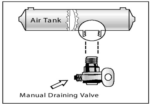
Figure 5.1
5.1.5 – Alcohol Evaporator
Some air brake systems have an alcohol evaporator to put alcohol into the air system. This helps to reduce the risk of ice in air brake valves and other parts during cold weather. Ice inside the system can make the brakes stop working.
Check the alcohol container and fill up as necessary. (every day during cold weather). Daily air tank drainage is still needed to get rid of water and oil (unless the system has automatic drain valves).
5.1.6 – Safety Valve
A safety relief valve is installed in the first tank the air compressor pumps air to. The safety valve protects the tank and the rest of the system from too much pressure. The valve is usually set to open at 150 psi. If the safety valve releases air, something is wrong. Have the fault fixed by a mechanic.
5.1.7 – The Brake Pedal
You engage the brakes by pushing down the brake pedal (It is also called a foot valve or treadle valve). Pushing the pedal down harder applies more air pressure. Letting up on the brake pedal reduces the air pressure and releases the brakes. Releasing the brakes lets some compressed air go out of the system, so the air pressure in the tanks is reduced. It must be made up by the air compressor. Pressing and releasing the pedal unnecessarily can let air out faster than the compressor can replace it. If the pressure gets too low, the brakes will not work.
5.1.8 – Foundation Brakes
Foundation brakes are used at each wheel. The most common type is the S-cam drum brake. The parts of the brake are discussed below.
Brake Drums, Shoes, and Linings. Brake drums are located on each end of the vehicle’s axles. The wheels are bolted to the drums. The braking mechanism is inside the drum. To stop, the brake shoes and linings are pushed against the inside of the drum. This causes friction, which slows the vehicle (and creates heat). The heat a drum can take without damage depends on how hard and how long the brakes are used. Too much heat can make the brakes stop working.
S-cam Brakes. When you push the brake pedal, air is let into each brake chamber. Air pressure pushes the rod out, moving the slack adjuster, thus twisting the brake camshaft. This turns the S-cam (it is shaped like the letter “S”). The S-cam forces the brake shoes away from one another and presses them against the inside of the brake drum. When you release the brake pedal, the S-cam rotates back and a spring pulls the brake shoes away from the drum, letting the wheels roll freely again. See Figure 5.2.
CamLaster. The CamLaster brake has 2 key design differences over traditional S-cam brakes.
One feature is a completely internal adjustment system which is designed to continually keep the brake in proper adjustment. S-cam brakes, on the other hand, require an external slack adjuster. The second feature is a unique cam design that applies the brake shoe. Unlike a standard drum brake that has either a single or double anchor-pin brake, the CamLaster slides the shoes down an inclined ramp on a cam to evenly contact the brake drum.
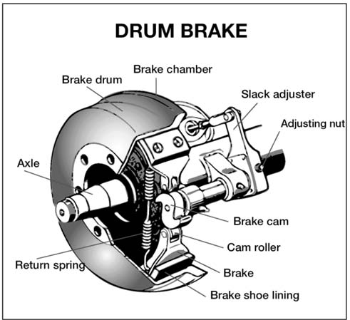
Figure 5.2
Wedge Brakes. In this type of brake, the brake chamber push rod pushes a wedge directly between the ends of 2 brake shoes. This shoves them apart and against the inside of the brake drum. Wedge brakes may have a single brake chamber or 2 brake chambers that push wedges in at both ends of the brake shoes. Wedge type brakes may be self-adjusting or may require manual adjustment.
Disc Brakes. In air-operated disc brakes, air pressure acts on a brake chamber and slack adjuster, like S-cam brakes. But instead of the S-cam, a “power screw” is used. The pressure of the brake chamber on the slack adjuster turns the power screw. The power screw clamps the disc or rotor between the brake lining pads of a caliper, similar to a large c-clamp.
Wedge brakes and disc brakes are less common than S-cam brakes.
5.1.9 – Supply Pressure Gauges
All vehicles with air brakes have a pressure gauge connected to the air tank. If the vehicle has a dual air brake system, there will be a gauge for each half of the system (or a single gauge with two needles). Dual systems will be discussed later. These gauges tell you how much pressure is in the air tanks.
5.1.10 – Application Pressure Gauge
This gauge shows how much air pressure you are applying to the brakes. (This gauge is not on all vehicles.) Increasing application pressure to hold the same speed means the brakes are fading. You should slow down and use a lower gear. Brakes that are of adjustment, air leaks, or mechanical problems can also cause the need for increased pressure.
5.1.11 – Low Air Pressure Warning
A low air pressure warning signal is required on vehicles with air brakes. A warning signal you can see must come on when the air pressure in the tanks falls between 55 and 75 psi (or 1/2 the compressor governor cutout pressure on older vehicles). The warning is usually a red light. A buzzer may also come on.
Another type of warning is the “wig wag.” This device drops a mechanical arm into your view when the pressure in the system drops between 55 and 75 psi. An automatic wig wag will rise out of your view when the pressure in the system goes above 55 and 75 psi. The manual reset type must be placed in the “out of view” position manually. It will not stay in place until the pressure in the system is above 55 psi.
On large buses, it is common for the low pressure warning devices to signal at 80–85 psi.
5.1.12 – Stop Light Switch
Drivers behind you must be warned when you put your brakes on. The air brake system does this with an electric switch that works by air pressure. The switch turns on the brake lights when you put on the air brakes.
5.1.13 – Front Brake Limiting Valve
Some vehicles made before 1975 have a front brake limiting valve and a control in the cab. The control is usually marked “normal” and “slippery.” When you put the control in the “slippery” position, the limiting valve cuts the “normal” air pressure to the front brakes by half. Limiting valves were used to reduce the chance of the front wheels skidding on slippery surfaces. However, they actually reduce the stopping power of the vehicle. Front wheel braking is good under all conditions. Tests have shown front wheel skids from braking are not likely even on ice. Make sure the control is in the “normal” position to have normal stopping power.
Many vehicles have automatic front wheel limiting valves. They reduce the air to the front brakes except when the brakes are put on very hard (60 psi or more application pressure). The driver cannot control these valves.
5.1.14 – Spring Brakes
All trucks, truck tractors, and buses must be equipped with emergency brakes and parking brakes. They must be held on by mechanical force (because air pressure can eventually leak away). Spring brakes are usually used to meet these needs. Powerful springs are held back by air pressure when driving. If the air pressure is removed, the springs put on the brakes. A parking brake control in the cab allows the driver to let the air out of the spring brakes. This lets the springs put the brakes on. A leak in the air brake system, which causes all the air to be lost, will also cause the springs to put on the brakes.
Tractor and straight truck spring brakes will come fully on when air pressure drops to a range of 20 to 45 psi (typically 20 to 30 psi). Do not wait for the brakes to come on automatically. When the low air pressure warning light, and buzzer first come on, bring the vehicle to a safe stop right away, while you can still control the brakes.
The braking power of spring brakes depends on the brakes being in adjustment. If the brakes are not adjusted properly, neither the regular brakes nor the emergency/parking brakes will work right.
5.1.15 – Parking Brake Controls
In newer vehicles with air brakes, you put on the parking brakes using a diamond-shaped, yellow, push-pull control knob. You pull the knob out to put the parking brakes (spring brakes) on, and push it in to release them. On older vehicles, the parking brakes may be controlled by a lever. Use the parking brakes whenever you park.
Caution. Never push the brake pedal down when the spring brakes are on. If you do, the brakes could be damaged by the combined forces of the springs and the air pressure. Many brake systems are designed so this will not happen. Not all systems are set up that way, and those that are may not always work. It is much better to develop the habit of not pushing the brake pedal down when the spring brakes are on.
Modulating Control Valves. In some vehicles a control handle on the dash board may be used to apply the spring brakes gradually. This is called a modulating valve. It is spring-loaded so you have a feel for the braking action. The more you move the control lever, the harder the spring brakes come on. They work this way so you can control the spring brakes if the service brakes fail. When parking a vehicle with a modulating control valve, move the lever as far as it will go and hold it in place with the locking device.
Dual Parking Control Valves. When main air pressure is lost, the spring brakes come on. Some vehicles, such as buses, have a separate air tank which can be used to release the spring brakes. This is so you can move the vehicle in an emergency. One of the valves is a push-pull type and is used to put on the spring brakes for parking. The other valve is spring loaded in the “out” position. When you push the control in, air from the separate air tank releases the spring brakes so you can move. When you release the button, the spring brakes come on again. There is only enough air in the separate tank to do this a few times. Therefore, plan carefully when moving. Otherwise, you may be stopped in a dangerous location when the separate air supply runs out. See Figure 5.3.
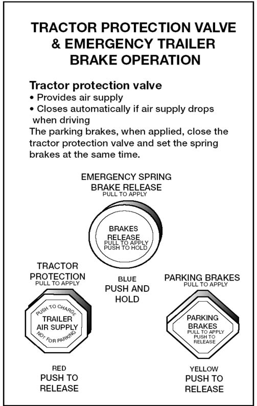
Figure 5.3
5.1.16 – Anti-lock Braking Systems
Truck tractors with air brakes built on or after March 1, 1997, and other air brakes vehicles (trucks, buses, trailers, and converter dollies) built on or after March 1, 1998, are required to be equipped with anti-lock brakes. Many commercial vehicles built before these dates have been voluntarily equipped with ABS. Check the certification label for the date of manufacture to determine if your vehicle is equipped with ABS. ABS is a computerized system that keeps your wheels from locking up during hard brake applications.
- Vehicles with ABS have yellow malfunction lamps to tell you if something is not working.
- Tractors, trucks, and buses will have yellow ABS malfunction lamps on the instrument panel.
- Trailers will have yellow ABS malfunction lamps on the left side, either on the front or rear corner. Dollies manufactured on or after March 1, 1998, are required to have a lamp on the left side.
On newer vehicles, the malfunction lamp comes on at start-up for a bulb check, and then goes out quickly. On older systems, the lamp could stay on until you are driving over 5 mph.
- If the lamp stays on after the bulb check, or goes on once you are under way, you may have lost ABS control at one or more wheels.
- In the case of towed units manufactured before it was required by the DOT, it may be difficult to tell if the unit is equipped with ABS. Look under the vehicle for the ECU and wheel speed sensor wires coming from the back of the brakes.
- ABS is an addition to your normal brakes. It does not decrease or increase your normal braking capability. ABS only activates when wheels are about to lock up.
- ABS does not necessarily shorten your stopping distance, but it does help you keep the vehicle under control during hard braking.
SUBSECTION 5.1
Test Your Knowledge
- Why must air tanks be drained?
- What is a supply pressure gauge used for?
- All vehicles with air brakes must have a low air pressure warning signal. True or False?
- What are spring brakes?
- Front wheel brakes are good under all conditions. True or False?
- How do you know if your vehicle is equipped with anti-lock brakes?
These questions may be on your test. If you cannot answer them all, reread Subsection 5.1.
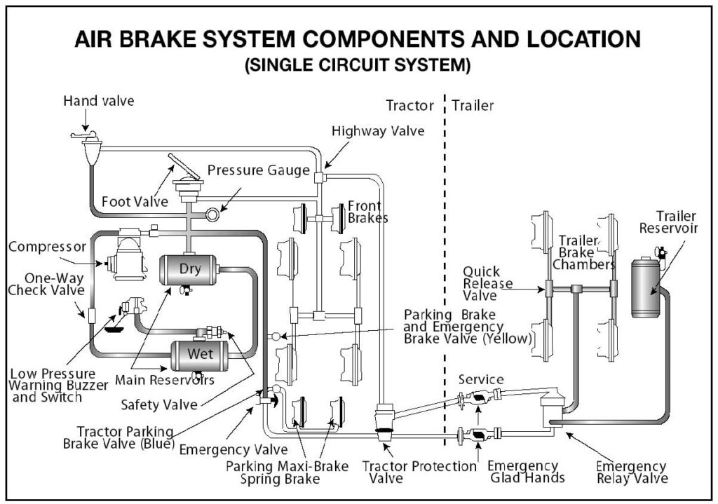
Figure 5.4
5.2 – Dual Air Brake
Most heavy-duty vehicles use dual air brake systems for safety. A dual air brake system has 2 separate air brake systems, which use a single set of brake controls. Each system has its own air tanks, hoses, lines, etc. One system typically operates the regular brakes on the rear axle or axles. The other system operates the regular brakes on the front axle (and possibly one rear axle). Both systems supply air to the trailer (if there is one). The first system is called the “primary” system. The other is called the “secondary” system. See Figure 5.4.
Before driving a vehicle with a dual air system, allow time for the air compressor to build up a minimum of 100 psi pressure in both the primary and secondary systems. Watch the primary and secondary air pressure gauges (or needles, if the system has 2 needles in one gauge). Pay attention to the low air pressure warning light and buzzer. The warning light and buzzer should shut off when air pressure in both systems rises to a value set by the manufacturer. This value must be greater than 55 psi.
The warning light and buzzer should come on before the air pressure drops below 55 psi in either system. If this happens while driving, you should stop right away and safely park the vehicle. If one air system is very low on pressure, either the front or the rear brakes will not be operating fully. This means it will take you longer to stop. Bring the vehicle to a safe stop, and have the air brakes system fixed.
One-Way Check Valve
This device allows air to flow in one direction only. All air tanks on air-brake vehicles must have a check valve located between the air compressor and the first reservoir (CVC §26507). The check valve keeps air from going out if the air compressor develops a leak.
5.3 – Inspecting Air Brake Systems
You should use the basic 7-step inspection procedure described in Section 2 to inspect your vehicle. There is more to inspect on a vehicle with air brakes than one without them. These components are discussed below, in the order that they fit into the 7-step method.
5.3.1 – During Step 2 Engine Compartment Checks
Check the air compressor drive belt (if the compressor is belt-driven). If the air compressor is belt-driven, check the condition and tightness of the belt. It should be in good condition.
5.3.2 – During Step 5 Walk Around Inspection
Check slack adjusters on S-cam brakes. Park on level ground and chock the wheels to prevent the vehicle from moving. Release the parking brakes so you can move the slack adjusters. Use gloves and pull hard on each slack adjuster that you can reach. If a slack adjuster moves more than about one inch where the push rod attaches to it, it probably needs adjustment. Adjust it or have it adjusted. Vehicles with too much brake slack can be very hard to stop. Out-of-adjustment brakes are the most common problem found in roadside inspections. Be safe. Check the slack adjusters.
All vehicles built since 1994 have automatic slack adjusters. Even though automatic slack adjusters adjust themselves during full brake applications, they must be checked.
Automatic adjusters should not have to be manually adjusted except when performing maintenance on the brakes and during installation of the slack adjusters. In a vehicle equipped with automatic adjusters, when the pushrod stroke exceeds the legal brake adjustment limit, it is an indication that a mechanical problem exists in the adjuster itself, a problem exists with the related foundation brake components, or the adjuster was improperly installed.
The manual adjustment of an automatic adjuster to bring a brake pushrod stroke within legal limits is generally masking a mechanical problem and is not fixing it. Further, routine adjustment of most automatic adjusters will likely result in premature wear of the adjuster itself. It is recommended that when brakes equipped with automatic adjusters are found to be out of adjustment, the driver takes the vehicle to a repair facility as soon as possible to have the problem corrected. The manual adjustment of automatic slack adjusters is dangerous because it may give the driver a false sense of security regarding the effectiveness of the braking system.
The manual adjustment of an automatic adjuster should only be used as a temporary measure to correct the adjustment in an emergency situation. It is likely the brake will soon be back out of adjustment since this procedure usually does not fix the underlying adjustment problem.
Note Automatic slack adjusters are made by different manufacturers and do not all operate the same. Therefore, the specific manufacturer’s service manual should be consulted prior to troubleshooting a brake adjustment problem.
Check Brake Drums (or Discs), Linings, and Hoses
Brake drums (or discs) must not have cracks longer than 1/2 the width of the friction area. Linings (friction material) must not be loose or soaked with oil or grease and must not be worn dangerously thin (less than 1/4 inch). Mechanical parts must be in place, not broken, or missing. Check the air hoses connected to the brake chambers to make sure they are not cut or worn due to rubbing.
5.3.3 – Step 7: Final Air Brake Check
All air brake system tests in this section are considered important and each can be considered critical parts of the in-cab air brakes tests. The items marked with an asterisk (*) in this section are required for testing purposes during the vehicle inspection portion of the CDL skills test. They may be performed in any order as long as they are performed correctly and effectively. If these items are not demonstrated and the parameters for each test are not verbalized correctly, it is considered an automatic failure of the vehicle inspection portion of the skills test.
Do the following checks instead of the hydraulic brake check shown in Section 2, Step 7: Check Brake System.
1. Applied Leakage Test (1-minute hold): *
To perform this test, the driver must start with the engine running and with the air pressure built to governor cut-out (120–140 psi or another level specified by the manufacturer). The driver identifies when cut-out occurred, shuts off the engine, chocks the wheels if necessary, releases the parking brake (all vehicles) and tractor protection valve (combination vehicle), and fully applies the foot brake. The driver then holds the foot brake for 1 minute after stabilization of the air gauge. The driver checks the air gauge to see that the air pressure drops no more than 3 pounds in one minute (single vehicle) or 4 pounds in 1 minute (combination vehicle) and listens for air leaks. The driver must identify how much air the system lost and verbalize the maximum air loss rate allowed for the representative vehicle being tested.
Note For a Class A combination vehicle, if the power unit is equipped with air brakes and the trailer is equipped with electric/surge brakes, the pressure drop should be no more than 3 psi.
- 3 psi for single vehicles.
- 4 psi for a combination of 2 vehicles.
- 6 psi for a combination of 3 or more vehicles.
Important The maximum air loss rate for a combination of 2 or more vehicles is 3 psi if the towed vehicles are not equipped with air brakes.
An air loss greater than those listed above, indicates a problem in the braking system and repairs are needed before operating the vehicle. If the air loss is too much, check for air leaks and fix any that are identified.
Note For testing purposes, you must be able to demonstrate this test and verbalize the allowable air loss for your vehicle. For testing purposes, identify if the air loss rate is too much.
2. Low Air Warning Device*
To perform this test the vehicle must have enough air pressure so the low-pressure warning signal is off. The engine maybe on or off; however, the key must be in the “on” or “battery charge” position. Next, the driver begins fanning off the air pressure by rapidly applying and releasing the foot brake. Low-air warning devices (buzzer, light, and flag) must activate before air pressure drops below 55 psi or the level specified by the manufacturer. The driver must indicate the approximate pressure when the device gave warning and identify the parameter at which this must occur; no lower than 55 psi. See Figure 5.5.
For testing purposes, identify and verbalize the pressure at which the low air pressure warning signal activates and identify the parameter(s) at which this should occur. On large buses, it is common for low-pressure warning devices to signal at 80–85 psi. If testing in a large bus, identify the parameter(s) mentioned above (55–75 psi) and inform the examiner that your vehicle’s low-pressure warning devices are designed to activate at a higher pressure.
If the warning signal does not work, you could lose air pressure and not know it. This could cause sudden emergency braking in a single-circuit air system. In dual systems, the stopping distance will be increased. Only limited braking can be done before the spring brakes come on.
Note Farm labor vehicles and Type I school buses must be equipped with both an audible and visible type warning device.
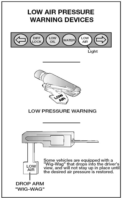
Figure 5.5
3. Spring Brake Test:*
To perform this test, the parking brake (all vehicles) and tractor protection valve (combination vehicles) must be released; (engine running or not) as the driver fans off the air pressure. Normally between 20-45 psi (or the level specified by the manufacturer) on a tractor-trailer combination vehicle, the tractor protection valve and parking brake valve should close (pop out). On other combination vehicle types and single vehicle types, the parking brake valve should close (pop out). The driver must identify and verbalize the approximate pressure at which the brake(s) activated.
Note The parking brake valve will not pop out on buses that are equipped with an emergency park brake air reservoir (tank). If your bus is equipped with an emergency park brake air tank, you must perform the spring brake test for triple reservoir vehicles to check the automatic actuation of the spring brakes.
Spring Brake Test for Triple Reservoir Vehicles
If the parking brake valve does not pop out when the air pressure has been reduced to approximately 20 psi, you must demonstrate that the spring brakes have activated. To do this, you must:
- Remove the wheel chocks, if necessary.
- Leave the parking brake valve in the open (released) position.
- With the engine running, put the vehicle in a forward gear and attempt to drive forward.
The spring brakes should drag and prevent the vehicle from easily moving forward. If the spring brakes do not prevent the vehicle from easily moving forward, your road test will be postponed.
Note This test must only be performed on single vehicles designed with an isolated parking brake reservoir. Do not perform this test on combination vehicles.
Check the Rate of Air Pressure Buildup
To perform this test, the engine must be running at normal operating idle, typically 600–900 rpms. Observe the air gauge to determine if the pressure builds at the proper rate. For dual air systems, the pressure should build from approximately 85 to 100 psi within 45 seconds. For single air systems (in pre-1975 vehicles), the pressure should build from approximately 50 to 90 psi within 3 minutes.
For testing purposes, you must verbalize the parameters of the test and identify if the vehicle met the appropriate standards.
Test Air Leakage Rate
There are 3 tests as follows:
Static Leakage Test
With a basically fully-charged air system (within the effective operating range for the compressor), turn off the engine, release all brakes, and let the system settle (air gauge needle stops moving). Time for 1 minute. The air pressure should not drop more than:
- 2 psi for single vehicles.
- 3 psi for a combination of 2 vehicles.
- 5 psi for a combination of 3 or more vehicles.
Important The maximum air loss rate for a combination of 2 or more vehicles is 2 psi if the towed vehicles are not equipped with air brakes.
An air loss greater than those listed above, indicate a problem in the braking system and repairs are needed before operating the vehicle.
Test Parking Brake
Fasten your seat belt. Set the parking brake, and gently pull against it in a low gear to test that the parking brake will hold.
Test Service Brakes
Wait for normal air pressure, release the parking brake, move the vehicle forward slowly (about 5 mph), and apply the brakes firmly using the brake pedal. Note any vehicle “pulling” to one side, unusual feel, or delayed stopping action.
This test may show you problems, which you otherwise would not know about until you needed the brakes on the road.
SUBSECTIONS 5.2 AND 5.3
Test Your Knowledge
- What is a dual air brake system?
- What are the slack adjusters?
- How can you check slack adjusters?
- How can you test the low pressure warning signal?
- How can you check the spring brakes come on automatically?
- What are the maximum leakage rates?
These questions may be on your test. If you cannot answer them all, reread Subsections 5.2 and 5.3.
5.4 – Using Air Brakes
5.4.1 – Normal Stops
Push the brake pedal down. Control the pressure so the vehicle comes to a smooth, safe stop. If you have a manual transmission, do not push the clutch in until the engine rpm is down close to idle. When stopped, select a starting gear.
5.4.2 – Braking With Anti-lock Brakes
- When you brake hard on slippery surfaces in a vehicle without ABS, your wheels may lock up. When your steering wheels lock up, you lose steering control. When your other wheels lock up, you may skid, jackknife, or even spin the vehicle.
- ABS helps you avoid wheel lock up. The computer senses impending lockup, reduces the braking pressure to a safe level, and helps you maintain control.
- You may or may not be able to stop faster with ABS, but you should be able to steer around an obstacle while braking, and avoid skids caused by over braking.
- Having ABS on only the tractor, only the trailer, or even on only 1 axle, still gives you more control over the vehicle during braking. Brake normally.
- When only the tractor has ABS, you should be able to maintain steering control, and there is less chance of jackknifing. But keep your eye on the trailer and let up on the brakes (if you can safely do so) if it begins to swing out.
- When only the trailer has ABS, the trailer is less likely to swing out. But if you lose steering control or start a tractor jackknife, let up on the brakes (if you can safely do so) until you gain control.
- When you drive a tractor-trailer combination with ABS, you should brake as you always have. In other words:
— Use only the braking force necessary to stop safely and stay in control.
— Brake the same way, regardless of whether you have ABS on the tractor, the trailer, or both.
— As you slow down, monitor your tractor and trailer and back off the brakes (if it is safe to do so) to stay in control.
— There is only 1 exception to this procedure. If you always drive a straight truck or combination with working ABS on all axles, in an emergency stop, you can fully apply the brakes.
— Without ABS, you still have normal brake functions. Drive and brake as you always have.
— Remember, if your ABS malfunctions, you still have regular brakes. Drive normally, but get the system serviced soon.
5.4.3 – Emergency Stops
If somebody suddenly pulls out in front of you, your natural response is to hit the brakes. This is a good response if there is enough distance to stop, and you use the brakes correctly.
You should brake in a way that will keep your vehicle in a straight line and allow you to turn if it becomes necessary. You can use the “controlled braking” or “stab braking” method.
Controlled Braking. With this method, you apply the brakes as hard as you can without locking the wheels. Keep steering wheel movements very small while doing this. If you need to make a larger steering adjustment or if the wheels lock, release the brakes. Reapply the brakes as soon as you can.
Stab Braking. Apply your brakes all the way. Release the brakes when wheels lock up. As soon as the wheels start rolling, apply the brakes fully again. (It can take up to one second for the wheels to start rolling after you release the brakes. If you reapply the brakes before the wheels start rolling, the vehicle will not straighten out.)
5.4.4 – Stopping Distance
Stopping distance was described in Section 2.6 under “Speed and Stopping Distance.” With air brakes there is an added delay, “brake lag”. This is the time required for the brakes to work after the brake pedal is pushed. With hydraulic brakes (used on cars and light/medium trucks), the brakes work instantly. However, with air brakes, it takes a little time (one half second or more) for the air to flow through the lines to the brakes. Thus, the total stopping distance for vehicles with air brake systems is made up of 4 different factors.
Perception Distance + Reaction Distance + Brake Lag Distance + Braking Distance = Total Stopping Distance
The air brake lag distance at 55 mph on dry pavement adds about 32 feet. Therefore, at 55 mph for an average driver under good traction and brake conditions, the total stopping distance is over 450 feet. See Figure 5.6.
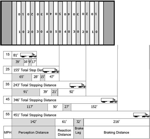
Figure 5.6
5.4.5 – Brake Fading or Failure
Brakes are designed so that brake shoes or pads rub against the brake drum or discs to slow the vehicle. Braking creates heat, but brakes are designed to take a lot of heat. However, brakes can fade or fail from excessive heat caused by using them too much and not relying on the engine braking effect.
Excessive use of the service brakes results in overheating and leads to brake fade. Brake fade results from excessive heat causing chemical changes in the brake lining, which reduce friction, and cause expansion of the brake drums. As the overheated drums expand, the brake shoes and linings have to move farther to contact the drums, and the force of this contact is reduced. Continued overuse may increase brake fade until the vehicle cannot be slowed down or stopped.
Brake fade is also affected by adjustment. To safely control a vehicle, every brake must do its share of the work. Brakes out of adjustment will stop doing their share before those that are in adjustment. The other brakes can then overheat and fade, and there will not be enough braking available to control the vehicle(s). Brakes can get out of adjustment quickly, especially when they are hot. Therefore, check brake adjustment often.
5.4.6 – Proper Braking Technique
Remember, the use of brakes on a long and/or steep downgrade is only a supplement to the braking effect of the engine. Once the vehicle is in the correct low gear, the following is the proper braking technique:
- Apply the brakes just hard enough to feel a definite slowdown.
- When your speed has been reduced to approximately 5 mph below your “safe” speed, release the brakes. (This application should last for about 3 seconds.)
When your speed has increased to your “safe” speed, repeat steps 1 and 2.
If your “safe” speed is 40 mph, you would not apply the brakes until your speed reaches 40 mph. You now apply the brakes hard enough to gradually reduce your speed to 35 mph and then release the brakes. Repeat this as often as necessary until you have reached the end of the downgrade.
5.4.7 – Low Air Pressure
If the low air pressure warning comes on, stop and safely park your vehicle as soon as possible. There might be an air leak in the system. Controlled braking is possible only while enough air remains in the air tanks. The spring brakes will come on when the air pressure drops into the range of 20 to 45 psi. A heavily loaded vehicle will take a long distance to stop because the spring brakes do not work on all axles. Lightly loaded vehicles or vehicles on slippery roads may skid out of control when the spring brakes come on. It is much safer to stop while there is enough air in the tanks to use the foot brakes.
5.4.8 – Parking Brakes
Any time you park, use the parking brakes, except as noted below. Pull the parking brake control knob out to apply the parking brakes and push it in to release. The control will be a yellow, diamond-shaped knob labeled “parking brakes” on newer vehicles. On older vehicles, it may be a round blue knob or some other shape (including a lever that swings from side to side or up and down).
- Do not use the parking brakes if the brakes are very hot (from just having come down a steep grade), or if the brakes are very wet in freezing temperatures. If they are used while they are very hot, they can be damaged by the heat. If they are used in freezing temperatures when the brakes are very wet, they can freeze so the vehicle cannot move. Use wheel chocks on a level surface to hold the vehicle. Let hot brakes cool before using the parking brakes. If the brakes are wet, use the brakes lightly while driving in a low gear to heat and dry them.
- If your vehicle does not have automatic air tank drains, drain your air tanks at the end of each working day to remove moisture and oil. Otherwise, the brakes could fail.
Never leave your vehicle unattended without applying the parking brakes or chocking the wheels. Your vehicle might roll away and cause injury and damage.
SUBSECTION 5.4
Test Your Knowledge
- Why should you be in the proper gear before starting down a hill?
- What factors can cause brakes to fade or fail?
- The use of brakes on a long, steep downgrade is only a supplement to the braking effect of the engine. True or False?
- If you are away from your vehicle only a short time, you do not need to use the parking brake. True or False?
- How often should you drain air tanks?
- How do you brake when you drive a tractor-trailer combination with ABS?
- You still have normal brake functions if your ABS is not working. True or False?
These questions may be on your test. If you cannot answer them all, reread Subsection 5.4.